Building a resilient and scalable system with microservices is like constructing a modern metropolis. Without a clear blueprint, you risk creating a chaotic, unmanageable tangle of services. The shift from monolithic structures to distributed systems introduces powerful flexibility but also significant challenges in communication, data consistency, and fault tolerance. This is where established microservices architecture patterns become indispensable tools for any architect or engineer.
These patterns are reusable design approaches to recurring distributed-systems problems. They provide a vocabulary for discussing routing, data ownership, consistency, and failure isolation, but they are not guarantees. Each pattern adds operational and cognitive costs, and its value depends on workload characteristics, service boundaries, failure modes, and the team’s ability to operate it.
This comprehensive guide moves beyond simple definitions to provide actionable insights. We will dissect nine crucial microservices architecture patterns, from the foundational Database per Service to the sophisticated Saga Pattern for managing transactions. As explored in our previous posts on decentralized data concepts, these patterns are key to building modern systems. We'll equip you with practical examples and implementation tips. You will learn not just what these patterns are, but how and when to apply them effectively, enabling you to build scalable, maintainable, and fault-tolerant systems. This article provides the blueprint you need to navigate the complexities of distributed systems and build for the future.
1. API Gateway Pattern

The API Gateway is one of the most fundamental microservices architecture patterns, serving as a single, unified entry point for all client requests. It functions as a reverse proxy, accepting all incoming API calls, and then routing them to the appropriate internal microservice. This pattern simplifies the client-side experience by abstracting the complex, and often dynamic, backend system of distributed services.
Instead of clients needing to know the specific addresses of dozens of individual services, they communicate with one consistent gateway. This decouples the client from the microservices, allowing backend teams to refactor, update, or replace services without affecting the client application.
How It Works and Use Cases
The gateway intercepts requests and handles various cross-cutting concerns that would otherwise need to be implemented in every single microservice. This centralization dramatically reduces code duplication and complexity.
Practical Example: Consider a food delivery app. When a user opens the app, their device makes a single call to an API Gateway. The gateway then invokes the User Service for authentication, the Restaurant Service to fetch nearby restaurants, and the Order Service to get the user's order history. It then aggregates these responses into a single payload for the app, reducing network chattiness and simplifying client-side logic.
Key Responsibilities and Use Cases:
- Request Routing: The primary function is to route incoming requests to the correct downstream service. For example, a request to
/api/orderswould be directed to the Order Service, while/api/usersgoes to the User Service. - Edge authentication and policy enforcement: A gateway can validate credentials, apply quotas, and reject unauthorized edge requests. Internal services must still enforce authorization for their own resources and should not assume that every caller reached them through the gateway.
- Rate Limiting and Throttling: It protects backend services from being overwhelmed by enforcing usage policies and limiting the number of requests a client can make in a given timeframe.
- Protocol Translation: A common use case is translating client-facing protocols like REST (HTTP) to internal protocols used by microservices, such as gRPC or AMQP.
- Response Aggregation: As seen in the food delivery example, the gateway can compose responses from multiple services into one. This is sometimes known as the "Gateway Aggregation Pattern".
For more insights on how this fits into broader system designs, you can explore other essential cloud architecture patterns.
Actionable Implementation Tips
- Keep domain policy out of the gateway: Routing, protocol adaptation, authentication, and client-specific aggregation can belong at the edge. Business invariants and resource authorization belong with the service that owns the domain data.
- Implement Resilience Patterns: The gateway is a critical component. Use circuit breakers (like Resilience4j) to prevent a failing microservice from cascading failures. Add health checks to automatically route traffic away from unhealthy service instances.
- Plan for Scalability: Since all traffic flows through the gateway, it must be highly available and scalable. Deploy multiple instances of the gateway behind a load balancer to ensure no single point of failure.
- Monitor Everything: Closely monitor gateway metrics like request latency, error rates, and resource utilization. This data is invaluable for troubleshooting performance issues and identifying system-wide problems.
2. Service Mesh Pattern

A service mesh is an infrastructure layer for applying traffic, security, and telemetry policy to service-to-service communication. It separates a data plane, which mediates workload traffic, from a control plane, which distributes configuration and policy.
A sidecar proxy beside every workload is one implementation, not the definition of a mesh. Current Istio supports both sidecar mode and ambient mode, where node-level proxies provide Layer 4 functions and optional waypoint proxies provide Layer 7 policy. Treat the choice as an operational trade-off involving feature coverage, isolation, resource cost, and failure scope.
How It Works and Use Cases
A service mesh consists of a "data plane" (the sidecar proxies like Envoy) and a "control plane" (the management layer like Istio). The control plane configures the proxies to enforce policies and collect telemetry, while the data plane executes those policies by routing traffic between services. This separation of concerns is key to its power.
Practical Example: An e-commerce platform wants to perform a canary release for its new Checkout Service v2. Using a service mesh like Istio, the operations team can configure a routing rule in the control plane to send 95% of traffic to v1 and 5% to v2. The sidecar proxies automatically enforce this rule without any code changes in the Checkout or calling services. The team can monitor v2's performance and error rate via the mesh's telemetry before gradually increasing its traffic share.
Key Responsibilities and Use Cases:
- Service Discovery and Load Balancing: The mesh automatically discovers new service instances and intelligently distributes requests across them, improving resilience and performance.
- Resilience controls: Depending on the mesh and data-plane mode, operators can configure timeouts, retries, outlier detection, and traffic shifting. These controls still require workload-specific limits and testing; an aggressive retry policy can amplify an outage.
- Observability: The mesh automatically collects detailed metrics, logs, and traces for all traffic, providing deep insights into service performance and behavior. This is crucial for debugging complex distributed systems.
- Secure Communication: It can enforce mutual TLS (mTLS) between services, encrypting all in-transit traffic and ensuring that only authorized services can communicate with each other.
- Advanced Traffic Management: As seen in the example, a service mesh enables powerful routing strategies like canary deployments and A/B testing.
To understand the broader trend toward decentralized control, you can explore these decentralized concepts further.
Actionable Implementation Tips
- Start with Basic Features: Don't try to implement every advanced policy at once. Begin with foundational features like mTLS for security and telemetry for observability. Gradually introduce more complex traffic routing rules as your team gains experience.
- Monitor Proxy Resource Consumption: Sidecar proxies consume CPU and memory. Closely monitor their resource footprint to ensure they don't negatively impact your application's performance. Set appropriate resource limits and requests in your deployment configurations.
- Implement Gradual Rollout Strategies: Introduce the service mesh into your environment incrementally. Start by adding it to a few non-critical services first, validate its behavior, and then expand the rollout across your application landscape.
- Ensure Proper Certificate Management: Secure communication (mTLS) relies on certificates. Use the mesh’s built-in certificate authority (CA) or integrate it with your existing PKI to automate certificate rotation and management, preventing outages due to expired certificates.
3. Circuit Breaker Pattern
The Circuit Breaker is an essential resilience pattern in microservices architecture designed to prevent a network or service failure from cascading to other services. Much like an electrical circuit breaker, it monitors calls to a remote service and, if failures exceed a certain threshold, it "trips" or opens the circuit. This immediately stops further requests to the failing service, allowing it to recover without overwhelming it with new, doomed-to-fail requests.
This pattern is a critical defense mechanism in distributed systems where one service's failure can quickly lead to system-wide outages. By isolating the failing component, the circuit breaker allows the rest of the system to continue functioning, albeit in a potentially degraded state, thereby improving overall system stability and user experience.
How It Works and Use Cases
A circuit breaker acts as a proxy or state machine for operations that are prone to failure, such as network calls. It operates in three states: Closed, Open, and Half-Open, managing the flow of requests based on the health of the downstream service.
Practical Example: A Product Detail page needs to call a Review Service to display customer reviews. If the Review Service becomes slow or unresponsive, the circuit breaker in the Product Detail service will trip after a few failed attempts. Subsequent page loads will immediately fail the call to the Review Service and instead execute a fallback: displaying the product details without the review section or showing a cached version. This prevents the entire product page from failing and gives the Review Service time to recover.
Key Responsibilities and Use Cases:
- Preventing Cascading Failures: Its primary use is to stop a chain reaction of failures. If a payment service is down, the circuit breaker prevents the order and shipping services from continuously retrying calls, which would consume their own resources.
- Graceful Degradation: When a circuit is open, the application can execute fallback logic, as seen in the example.
- Automatic Recovery: After a timeout period, the breaker moves to a half-open state, allowing a limited number of test requests to pass through. If these succeed, the breaker returns to the closed state, resuming normal operation. If they fail, it remains open.
- Latency Protection: It can be configured to trip based on response times. If a service becomes unacceptably slow, the circuit breaker can open to prevent slow responses from bogging down the entire system.
These tools are crucial for building robust systems, complementing strategies discussed in network security and resilience.
Actionable Implementation Tips
- Configure Thresholds Wisely: Set appropriate failure thresholds and timeouts based on the service's specific SLA and typical performance metrics. A threshold that is too low may cause the circuit to open unnecessarily, while one that is too high might not prevent a cascading failure in time.
- Implement Meaningful Fallbacks: A fallback should provide a reasonable alternative. This could be returning cached data, a default value, or a user-friendly message explaining that a feature is temporarily unavailable. Avoid generic error messages.
- Monitor the Breaker's State: Actively monitor the state of your circuit breakers. Alerts on state changes (e.g., from Closed to Open) can provide early warnings of system instability, allowing teams to investigate issues proactively.
- Coordinate retries with the breaker: Retry only failures that are likely to be transient, use bounded attempts with backoff and jitter, and make retried operations idempotent or deduplicated. Invoke attempts through the circuit breaker so that repeated failures contribute to opening the circuit, and apply an aggregate retry budget to avoid retry storms.
4. Saga Pattern
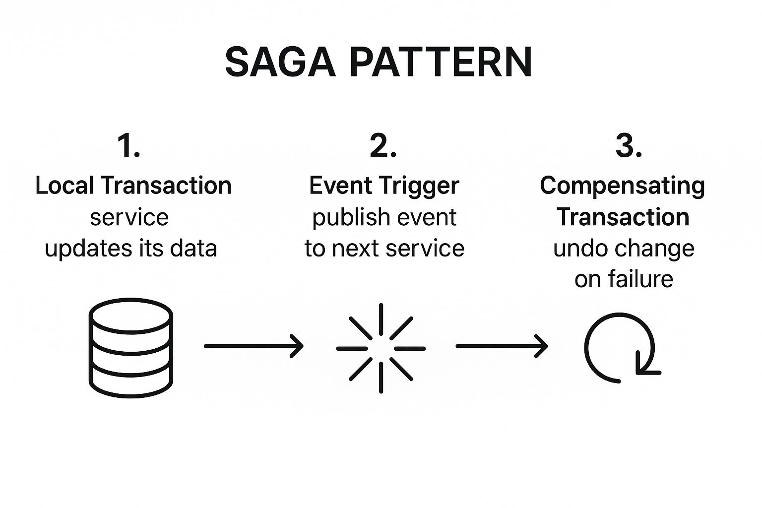
The Saga pattern is a crucial failure management pattern for maintaining data consistency across multiple microservices without relying on traditional two-phase commit (2PC) protocols, which are often impractical in distributed systems. It manages a sequence of local transactions, where each transaction updates data within a single service and then publishes an event or message that triggers the next local transaction in the chain.
If a step fails, a saga can initiate compensating transactions for earlier steps. Compensation is a new business action, not an ACID rollback: it may not restore the exact prior state, may itself fail, and can require retries, deduplication, reconciliation, or human intervention.
This infographic illustrates the core workflow, showing how a local transaction's success triggers the next step, while failure initiates a compensating transaction to maintain data integrity.
The visualization highlights the pattern's event-driven nature and its built-in mechanism for rollback, which is essential for handling failures in distributed operations.
How It Works and Use Cases
A saga is essentially a state machine that coordinates the entire distributed transaction. It can be implemented in two primary ways: choreography, where services publish events that trigger actions in other services, or orchestration, where a central coordinator tells each service what local transaction to execute.
Practical Example: A flight booking system needs to book a flight, reserve a hotel, and rent a car. This is a saga.
- Transaction 1: The
Booking Serviceinitiates the saga and tells theFlight Serviceto reserve a seat. - Transaction 2: If successful, the
Flight Serviceconfirms, and the saga tells theHotel Serviceto book a room. - Transaction 3: The
Hotel Servicefails because no rooms are available. - Compensating Transaction: The saga executes a compensating transaction, telling the
Flight Serviceto cancel the seat reservation, thus undoing the first step and leaving the system in a consistent state.
Key Responsibilities and Use Cases:
- Distributed Transaction Management: Its primary use is for operations that span multiple services, like placing an order in an e-commerce system.
- Coordinating consistency: A saga provides a structure for completing or compensating a multi-service operation. Eventual convergence depends on durable messaging, idempotent handlers, observable state, and recovery procedures.
- Failure Recovery: As shown in the example, if any step fails, the saga triggers compensating transactions to prevent data corruption.
- Long-Running Processes: It is ideal for processes that may take a long time to complete and involve multiple asynchronous steps, such as a customer onboarding workflow.
Understanding this pattern is key to overcoming many modern data integration challenges.
Actionable Implementation Tips
- Design Idempotent Compensating Operations: A compensating transaction might be retried if it fails. Ensure these operations are idempotent, meaning they can be executed multiple times without changing the result beyond the initial application (e.g., "cancel flight booking" can be called multiple times safely).
- Implement Comprehensive Logging and Monitoring: Since sagas are complex and distributed, robust logging is non-negotiable. Track the state of each saga instance to easily diagnose and troubleshoot failures.
- Use Semantic Locks to Prevent Race Conditions: To prevent inconsistent updates during a long-running saga, you can implement a "semantic lock." This involves adding a flag (e.g.,
status: PENDING_UPDATE) to a record to signal that it's part of an active saga, preventing other processes from modifying it. - Consider Using a Saga Orchestrator: For complex sagas with many steps, a centralized orchestrator (like AWS Step Functions or Camunda) simplifies development by explicitly defining the workflow, rather than relying on a choreographed event chain.
5. Event Sourcing Pattern
Event Sourcing records domain state changes as an ordered, append-only stream of events. Current state is obtained from a projection or by rehydrating an entity from its events, often beginning from a snapshot rather than replaying its entire history.
The event stream can support historical reconstruction and new projections, but it is not automatically complete, tamper-proof, or compliant. Correctness depends on event design, authorization, integrity controls, schema evolution, retention, and operational recovery. Use the pattern only when preserving change history or rebuilding projections justifies its additional complexity.
How It Works and Use Cases
In an event-sourced system, every action that modifies data is captured as an event object, such as OrderCreated, ItemAddedToCart, or PaymentProcessed. These events are the single source of truth and are stored sequentially in an event store. The application's current state is a projection derived from replaying this event stream.
This preserves a history of recorded domain events. Whether that history qualifies as an audit record depends on completeness, access controls, tamper evidence, retention, and the applicable regulatory requirements.
Key Responsibilities and Use Cases:
- Complete Audit Trail: Because every state change is recorded, Event Sourcing is ideal for systems requiring high levels of auditability and compliance, such as financial trading platforms or medical records systems.
- Temporal Queries: It enables querying the state of the system at any point in the past. For example, a support agent could reconstruct a user's shopping cart exactly as it was at the time an error occurred.
- Debugging and Analytics: Developers can replay events to reproduce bugs and understand complex system behavior. The difference between historical analysis and real-time event handling is a key consideration, which you can explore further in a comparison of batch processing vs. stream processing.
- Decoupled Projections: The event stream can be consumed by multiple downstream services to create different "read models" or projections of the data, tailored for specific query needs.
Actionable Implementation Tips
- Design Events for Longevity: Events are immutable and part of your system's permanent record. Design them as simple data transfer objects (DTOs) and avoid including complex logic. Plan for schema evolution from the start by implementing event versioning strategies.
- Implement Snapshotting for Performance: Replaying millions of events to reconstruct an entity's state can be slow. Implement snapshotting, which periodically saves the current state. To rebuild the entity, you load the latest snapshot and then only replay the events that have occurred since.
- Ensure Proper Event Serialization: Choose a serialization format (like JSON, Avro, or Protocol Buffers) that is flexible and supports schema evolution. The format must be stable for the long term, as you will need to deserialize old events for years to come.
- Design privacy and retention before adoption: Immutable histories can conflict with deletion, correction, minimization, and retention obligations. Keep unnecessary personal data out of events, separate sensitive payloads where appropriate, document retention rules, and obtain jurisdiction-specific privacy advice rather than assuming encryption-key deletion alone satisfies every obligation.
6. CQRS (Command Query Responsibility Segregation) Pattern
The CQRS (Command Query Responsibility Segregation) pattern is a transformative approach within microservices architecture patterns that fundamentally separates read and write operations for a data store. Instead of a single model for both reading and updating data, CQRS uses two distinct models: one for updating state (Commands) and another for reading state (Queries).
This segregation allows for the independent optimization and scaling of read and write workloads. Commands are focused on processing transactions and enforcing business rules, while Queries are optimized for high-performance data retrieval and presentation. This separation is crucial in complex domains where the requirements for writing data (consistency, validation) are vastly different from the requirements for reading it (performance, varied formats).
How It Works and Use Cases
At its core, CQRS splits an application into two sides. The Command side handles all create, update, and delete requests. The Query side handles all read requests, providing data views or "projections" that are specifically tailored to the needs of the client, without the overhead of complex write-side logic.
CQRS requires separate command and query models, not necessarily separate databases or asynchronous synchronization. A basic implementation can use distinct code paths over one data store. Separate read and write stores add independent scaling and storage choices, but also introduce synchronization failure modes and potentially stale reads.
Key Responsibilities and Use Cases:
- Task-Based UIs: Applications where users perform a series of complex tasks benefit greatly. The command side can model these intricate business workflows, while the query side provides simple, fast data reads.
- High-Performance Read Requirements: E-commerce product catalogs or social media feeds need to serve a massive volume of reads with very low latency. CQRS allows the read model to be denormalized and stored in a highly optimized read-only database.
- Event-Driven Systems: CQRS pairs naturally with Event Sourcing. Commands generate events that are stored, and these events are then used to build and update the read models (projections) asynchronously.
- Collaborative Domains: In systems where many users are working on the same data, like a project management tool, CQRS helps manage complex write-side conflicts while still providing performant read access to all users.
Actionable Implementation Tips
- Start Simple, Evolve as Needed: You don't need separate physical databases from day one. Begin by separating the command and query models in your code. You can introduce separate data stores later when performance requirements demand it.
- Choose the Right Database for the Job: Leverage the pattern's flexibility. Use a transactional database like PostgreSQL for the write side to ensure data integrity, and a denormalized database like Elasticsearch or Redis for the query side to ensure speed.
- Plan consistency deliberately: Eventual consistency applies when separate stores are updated asynchronously; it is not inherent to every CQRS implementation. If projections are asynchronous, design the user experience for stale reads and monitor projection lag.
- Monitor Synchronization Lag: The time it takes for a change on the write side to be reflected on the read side is a critical health metric. Implement monitoring to track this lag and set up alerts to detect potential issues with your event handling process.
7. Bulkhead Pattern
The Bulkhead pattern is a critical design for building fault-tolerant and resilient microservices. Inspired by the partitioned sections (bulkheads) of a ship's hull, it isolates system elements into pools so that if one fails, the others can continue functioning. This prevents a single cascading failure from bringing down the entire application.
In a microservices architecture, this means partitioning resources like connection pools, thread pools, and memory. If a downstream service becomes slow or unresponsive, only the resources allocated to it will be consumed. This ensures other, unrelated services remain responsive and the overall system stays healthy, making it an essential tool among microservices architecture patterns.
How It Works and Use Cases
The pattern works by creating separate, isolated resource pools for each dependency or critical component. A failure or high load in one microservice will only exhaust the resources in its designated partition, protecting the rest of the system.
Practical Example: An airline booking portal calls three different services: FlightSearch, HotelSearch, and RentalCarSearch. Using the Bulkhead pattern, the portal allocates a separate thread pool for each of these external calls. If the HotelSearch service becomes extremely slow, it will only exhaust its own dedicated thread pool. The FlightSearch and RentalCarSearch calls, running in their own isolated pools, will remain fast and responsive, allowing users to continue booking flights and cars even when the hotel functionality is degraded.
Key Responsibilities and Use Cases:
- Failure Isolation: The primary use case is to contain failures. As seen in the example, a failing non-critical service doesn't take down critical ones.
- Resource Management: It allows for fine-grained control over resource allocation. You can assign more resources (e.g., larger thread pools) to high-priority services and fewer to less critical ones.
- Load Segregation: You can partition services based on their expected load or consumer type. For example, requests from mobile clients could be handled by one pool, while requests from internal batch processes are handled by another.
- Preventing Cascading Failures: By containing the impact of a slow or failing service, the Bulkhead pattern directly prevents the domino effect where one service's failure triggers failures in upstream services.
Actionable Implementation Tips
- Identify Critical vs. Non-Critical Services: Analyze your application to distinguish between essential services (e.g., checkout, authentication) and non-essential ones (e.g., analytics tracking, social media feeds). Allocate separate, protected resource pools for the critical services first.
- Size Bulkheads Appropriately: Size your thread pools or connection pools based on performance testing and the specific requirements of each service. Start with a conservative number and monitor it closely to tune it.
- Combine with Circuit Breakers: The Bulkhead pattern works best when paired with the Circuit Breaker pattern. When the resources in a bulkhead are exhausted, the circuit breaker can trip, immediately failing subsequent calls to the problematic service and preventing the partition from being overwhelmed.
- Monitor Each Partition: Implement detailed monitoring for each bulkhead. Track metrics like the number of active threads, queue size, and rejection rates. This data is vital for tuning bulkhead sizes and detecting problems before they escalate.
8. Database per Service Pattern
Each service should own its data and expose it through a defined contract; another service should not reach into the owner’s schema directly.
“Database per service” describes logical ownership. Separate services can use distinct schemas or private tables on shared database infrastructure when that operational trade-off is appropriate; a dedicated database server per service is not required.
This approach prevents the creation of a shared database monolith, which often becomes a major bottleneck and source of contention in distributed systems. By giving each service its own data store, development teams gain autonomy to choose the most suitable database technology (a SQL database for transactional data, a NoSQL database for unstructured content, etc.) for their specific needs, a practice known as polyglot persistence.
How It Works and Use Cases
In this pattern, the database is considered a private implementation detail of the microservice. If another service needs data, it must make an API call to the service that owns the data. This API acts as a durable contract, abstracting the underlying data schema and allowing it to evolve independently without breaking other services.
Practical Example: In a social-media application, a UserService owns profile data while a PostService owns posts and comments. Each service selects storage from its transaction, query, consistency, lifecycle, resilience, and operational requirements. A relational or non-relational database can be appropriate for either workload; the entity name alone does not determine the database. When the post service needs current profile data, it uses the user service’s contract rather than querying its schema directly.
Key Responsibilities and Use Cases:
- Data Encapsulation: A core use case is to enforce strong boundaries between services, as seen in the example.
- Technology Autonomy (Polyglot Persistence): Teams can select the best tool for the job. A
Product Catalog Servicemight use a document database like MongoDB, while aPayment Servicewould use a relational database like PostgreSQL for ACID transactions. - Independent Scalability: Each database can be scaled independently based on its specific load, IOPS, and storage requirements.
- Schema Evolution: Teams can change their service's database schema without coordinating with or affecting any other team, as long as the service's API contract remains stable.
Actionable Implementation Tips
- Choose Appropriate Database Types: Don't default to a single database technology for all services. Analyze the data model and access patterns of each service to select the right database, whether it's relational, document, key-value, or graph.
- Implement Data Synchronization Strategies: Since data is decentralized, you need a strategy for handling queries that span multiple services. Use patterns like the Saga Pattern for distributed transactions or implement a separate reporting database using an event-driven approach.
- Use Event-Driven Patterns for Consistency: For ensuring eventual consistency across services, use asynchronous messaging. When the
Order Servicecreates an order, it can publish anOrderCreatedevent, which other services can subscribe to and update their own local data stores accordingly. - Plan for Cross-Service Reporting: Centralized reporting can be challenging. Consider building a data warehouse that aggregates data from different services through an ETL process or by subscribing to event streams.
9. Strangler Fig Pattern
The Strangler Fig Application pattern incrementally replaces parts of a legacy system behind an interception or routing boundary. The replacement does not have to be microservices, and the interceptor does not have to be an API gateway; the essential idea is to redirect capabilities gradually while measuring behavior and retaining a rollback path.
This approach avoids the massive risk and complexity of a "big bang" rewrite. Instead of replacing the entire system at once, teams can deliver value incrementally, building and routing traffic to new services piece by piece. This allows for a smoother, more controlled, and less disruptive transition, making it one of the most practical microservices architecture patterns for modernizing existing systems.
How It Works and Use Cases
The core idea is to intercept requests bound for the monolith and redirect them to new microservices as they become available. An intermediary layer, often an API Gateway or a reverse proxy, is placed in front of the monolith to manage this traffic routing.
Practical Example: A large, monolithic e-commerce website wants to modernize its checkout process.
- Intercept: They place an API Gateway in front of the monolith. Initially, it routes all traffic (e.g.,
/products,/cart,/checkout) to the old system. - Build: They build a new, standalone
Checkout Service. - Redirect: They update the API Gateway's routing rules. Now, any request to
/checkoutis sent to the new microservice, while all other traffic still goes to the monolith. - Repeat: They continue this process, carving out the
/productsand/cartfunctionality into new services until the original monolith handles no traffic and can be safely retired.
Key Responsibilities and Use Cases:
- Incremental Modernization: The primary use case is migrating a large, complex monolithic application to microservices without interrupting service.
- Traffic Routing: A routing facade (like an API Gateway) is essential for gradually shifting traffic to new services.
- Data Synchronization: During the transition, both the new microservices and the old monolith may need to access the same data. This often requires complex data synchronization strategies to maintain consistency.
- Decoupling Functionality: By replacing one domain at a time, the pattern helps teams break down complex business logic into isolated, manageable services, reducing cognitive load.
Actionable Implementation Tips
- Start with Low-Risk Components: Begin by identifying and migrating components that have few dependencies and are not mission-critical. This allows the team to learn the process and build confidence before tackling more complex parts of the system.
- Use an API Gateway for Traffic Routing: Implement a robust API Gateway or reverse proxy to act as the "facade." This centralizes routing logic and makes it easy to switch traffic from the monolith to a new microservice with a simple configuration change.
- Plan Data Migration Carefully: Data is often the most challenging part of a migration. Decide early whether you will use data synchronization, a shared database, or an anti-corruption layer to keep the old and new systems in sync during the transition.
- Monitor Both Systems: Implement comprehensive monitoring for both the legacy monolith and the new microservices. Compare performance metrics and error rates to ensure the new service is performing correctly before completely switching over.
Microservices Patterns Comparison Matrix
| Pattern | Implementation Complexity 🔄 | Resource Requirements ⚡ | Potential benefit 📊 | Ideal Use Cases 💡 | Key Advantages ⭐ |
|---|---|---|---|---|---|
| API Gateway Pattern | Moderate - adds deployment complexity and potential bottlenecks | Medium - requires dedicated gateway infrastructure | Simplified client interface, centralized security and monitoring | Microservices with many clients needing unified access | Centralized cross-cutting concerns, protocol translation, improved security |
| Service Mesh Pattern | High - requires sidecar proxies and operational expertise | High - extra proxies increase resource usage | Enhanced service-to-service communication, observability, and security | Large-scale microservices requiring fine-grained traffic control | Language-agnostic, centralized policies, centrally managed transport policy, observability |
| Circuit Breaker Pattern | Low to Moderate - adds logic to service calls and monitoring | Low - minimal hardware overhead | Prevents cascading failures, improves resilience and user experience | Systems vulnerable to partial failures or unstable dependencies | Fast failure detection, resource conservation, fallback handling |
| Saga Pattern | High - complex compensating transactions and event handling | Medium - depends on message/event infrastructure | Maintains data consistency across distributed transactions without locks | Long-running distributed transactions across microservices | Resilient to partial failures, scalable, avoids distributed locks |
| Event Sourcing Pattern | High - requires event storage, replay mechanisms, and versioning | High - increased storage and processing needs | Complete audit trail, time-travel debugging, event-driven analytics | Applications requiring full history and auditability of state changes | Reconstructable recorded history, supports complex analytics, fits event-driven designs |
| CQRS Pattern | High - separate models for command and query with synchronization | Medium to High - additional databases and infrastructure | Optimized read/write scaling and security, simplified domain models | Systems with distinct read and write workloads needing performance tuning | Independent scaling, performance gains, security separation, flexible storage |
| Bulkhead Pattern | Moderate - resource partitioning and allocation management | Medium - duplicates resource pools | Prevents failure cascading, improves system resilience and availability | Critical systems requiring fault isolation across components | Maintains availability, resource isolation, prioritizes critical operations |
| Database per Service | Moderate - each service manages private databases with integration | Medium to High - multiple databases and infrastructure | Strong service boundaries, independent scaling, reduced coupling | Microservices requiring data encapsulation and technology diversity | Encapsulation, polyglot persistence, fault isolation, flexibility |
| Strangler Fig Pattern | Moderate to High - requires parallel system operation and migration tooling | Medium - running old and new systems concurrently | Safe, gradual migration from monolith to microservices | Incremental migration with reduced risk and continuous operation | Low-risk transition, incremental cutover and rollback path, progressive migration, learning opportunity |
Building Your Blueprint: From Patterns to Practice
We have navigated the complex yet powerful landscape of microservices architecture, exploring nine foundational patterns that serve as the bedrock for modern, distributed applications. From the orchestrated entry point provided by the API Gateway Pattern to the resilient isolation of the Bulkhead Pattern, each blueprint offers a strategic solution to a specific set of challenges. We've seen how patterns like Saga and Event Sourcing tackle data consistency in a decentralized world, while CQRS optimizes read and write operations for high-performance systems.
The core lesson from this exploration is that there is no one-size-fits-all solution. A successful microservices strategy is not about picking a single "best" pattern. Instead, it’s about creating a composite architecture, a tailored blueprint where different patterns are combined to meet your unique business requirements and technical constraints. The real art lies in understanding the trade-offs and synergies between them. For instance, you might use the Strangler Fig Pattern for a legacy migration, implement a Database per Service model for your new services, and protect them all with Circuit Breakers managed through a Service Mesh.
From Theory to Tangible Results
Transitioning from understanding these patterns to implementing them requires a shift in mindset and process. It’s not just an architectural change; it's a cultural one that embraces decentralization, automation, and continuous evolution.
Here are your actionable next steps to turn these microservices architecture patterns into practice:
- 1. Conduct a Context-Driven Assessment: Before selecting a pattern, map out your specific problem domain. Are you dealing with complex, multi-step transactions? The Saga pattern is your starting point. Is your primary goal to isolate failures and prevent cascading system-wide outages? Look to the Bulkhead and Circuit Breaker patterns.
- 2. Start Small and Iterate: Don't attempt a "big bang" adoption. Identify a single, low-risk business capability to implement as a microservice. Use this pilot project to experiment with a pattern, such as the API Gateway, to manage its exposure. This iterative approach allows your team to learn and adapt without jeopardizing the entire system.
- 3. Prioritize Observability: Microservices create a distributed system where monitoring is non-negotiable. From day one, implement comprehensive logging, metrics, and tracing. This visibility is essential for debugging issues that span multiple services, especially when using complex patterns like Event Sourcing.
- 4. Automate Your Infrastructure and Deployment: The operational overhead of managing numerous services can be overwhelming without robust automation. Your CI/CD pipeline becomes the lifeblood of your microservices ecosystem. For successful microservices adoption, implementing robust CI/CD pipelines is crucial; explore key continuous integration best practices to streamline your workflow and deployments.
The Strategic Value of Architectural Mastery
Mastering these microservices architecture patterns is more than an academic exercise; it’s a direct investment in your organization's agility and resilience. It empowers your teams to build systems that can scale independently, deploy frequently, and withstand failures gracefully. This architectural dexterity translates into a significant competitive advantage, enabling you to respond to market changes faster, innovate more freely, and deliver a more reliable experience to your users.
As you embark on this journey, remember that architecture is a living thing. The blueprint you design today will evolve. Embrace this evolution, foster a culture of learning, and use the powerful patterns we've discussed as your guide. They are the tools that will help you build not just software, but resilient, scalable, and future-proof digital platforms.
Primary references
- Microsoft Azure Architecture Center: microservices design patterns
- Microsoft: API gateways in microservices
- Microsoft: Saga pattern
- Microsoft: Compensating Transaction pattern
- Microsoft: transient-fault handling
- Microsoft: CQRS pattern
- Microsoft: Event Sourcing pattern
- Istio: sidecar and ambient data-plane modes
- Martin Fowler: Strangler Fig Application
Fact-check record
Reviewed September 4, 2026. Made the guide evergreen; corrected gateway security scope, sidecar-only mesh descriptions, retry composition, Saga compensation guarantees, Event Sourcing audit and privacy claims, CQRS storage and consistency requirements, Database-per-Service ownership, and Strangler Fig scope using current Microsoft, Istio, and Fowler references.

Historical comments from Datanizant
No public comments on this article
1 imported entry withheld from public display after manual spam and duplicate review. The source archive remains unchanged.